Page 1 of 2
Advice on Overdrive installation
Posted: Thu Mar 25, 2021 2:25 pm
by tonygunton
I have recently acquired a new (old stock) Type D Laycock Overdrive unit and have pre ordered an adapter plate in advance of new stock in manufacture.
I am intending to install this on my Jupiter; but where?
1 Conventionally it should go behind the gearbox and indeed the adapter plate will allow this. However, this involves dropping gearbox disassembling same and having driveshaft splined and keyway for O/D pump. I also believe that a chassis modification is also required.
2 I understand that it has also been mounted in the drive train fixed to the chassis with altered prop shaft that has been splined.
3 I also understand that it has effectively been attached to back axel but adds to the un-sprung weight.
The second and third options require the adapter plate modified to provide an oil tight unit, and bearing, the O/D haveing its own oil supply
A further consideration is the electrics. A simple switch with indicator will be sufficient for the O/D solenoid but how does one prevent engaging overdrive in lower gears. I can prevent engaging in reverse with a simple relay connected to the reverse light switch.
I should be obliged to hear from those that have installed an overdrive and their solutions.
Best Regards,
Tony Gunton KAS147
Re: Advice on Overdrive installation
Posted: Fri Mar 26, 2021 10:04 am
by Keith Clements
Try a search on overdrive (top right) There are 13 pages of results in the
JT Library search and 275 results in the
Archive search .
My rear fitting replacing rear propshaft. Modification to battery box required but original prop can be swapped back in about 45 minutes. Such change was done at race circuit when I was racing. Tested on Saharan and other Pirelli Marathons and many other long journeys. A revision of the mounting system 3 years ago removed the propshaft bearing housing and support and mounted the overdrive on the chassis rather than subframe to give more stability.
viewtopic.php?p=42545#p42545
viewtopic.php?p=24304#p24304
Here you can see the circuit diagram incorporating dash switch, reverse lock switch, clutch kick down switch, overdrive latch relays
download/file.php?id=3424&mode=view
If I was doing it again I would use a modern smaller overdrive that you should be able to fit in place of the front propshaft without much (or any) modification to chassis, floor, gearbox, or mountings .
This is a factory engineering drawing for the Javelin
viewtopic.php?p=29696#p29696
Use of stepping motor to compensate for wheel size and repositioning of speedo cable.
viewtopic.php?p=24709#p24709
Re: Advice on Overdrive installation
Posted: Fri Mar 26, 2021 1:04 pm
by p.p.
i got a Laycock Overdrive Type D recondition for sale....
regards
peter
Re: Advice on Overdrive installation
Posted: Wed Mar 31, 2021 9:27 am
by Chris Spencer
I have spoken to several owners in regards to the overdrive installation on the Jupiter - I have also held long & detailed conversations with overdrive suppliers & specialists along with members involved in the supply of spares - I have a dedicated interest in the subject - owning 2 Jupiter's that I would like to fit the conversion to alongside several clients that would like the same conversion - Through my involvement with the club, Jowett ownership along with the fact that I run a small restoration its in my interests - Firstly the one size fits all adaptor plate will be difficult to make work - to have various different OD units of different sizes, lengths, mounting locations means that you have to have different lengths of propshafts for each conversion, different mountings bespoke fabricated and in some cases have to alter / modify the chassis & bulkhead of the car to make the OD unit fit.
Drummund Black has run a successful OD conversion for a significant number of years on his Jupiter - It involves a custom adaptor plate & gearbox conversion to mount the LH Type OD unit into the same space has the original Jowett gearbox - does not require any chassis or bulkhead modification - does not require the propshaft lengthening or shortening and if you ever get a problem a standard Jowett gearbox will fit straight into the space that you remove a converted gearbox & OD unit from - The LH OD unit is the strongest & most market available unit too as it was fitted to the MGB
I currently have all the parts with a fabrication engineer in order to produce the adaptor plate - I currently have a Jupiter that I'm restoring that the first conversion will be fitted to later this year - I see this has a tried & tested one stop solution to the OD conversion for the Jupiter that can be made available to the market - why on earth others are still messing around with J / D Type overdrives / adaptor plates that involve chassis & body modifications along with the fact they are largely unproven is a complete mystery to me - Surely the sensible route is to use a proven one stop OD conversion
Just to conclude - this is not a marketing effort on my behalf (I have enough forward workload /orders for the significant future) - its about finding the correct solution for the problem without reinventing the problem that you started with
Re: Advice on Overdrive installation
Posted: Sun Apr 11, 2021 1:20 am
by PJGD
Chris,
I too am interested in overdrive conversions for my Jupiter [877], and if as you say the LH version fits without chassis modifications, then that sounds like the optimum way to go. Presently, I have a GKN J-Type overdrive which was intended to be used with the modified gearbox mainsheet and adapter plate from a batch that, I believe it was Ken West if memory serves, had made many years ago. I have not actually built this up into a gearbox, as you can see from this photo, but that was the intent:
One of the things that I have done is to look at whether the overdrive goes best with a wide ratio or a close ratio gearbox and to that end I have assembled the basic data and plotted the ratios for both gearboxes. This compilation assumes the standard Jupiter axle ratio and tire size; I can adjust the input data to address non-standard ratios:
The gear ratio step size graph needs some explanation: It is plotting the step size from 1st gear to the next higher gear, and then the next gear, etc. including the overdrive ratios expressed as a percentage. Usually, in the normal driving range, a step size around 30% is a good target. In this case, I have plotted two overdrive ratios: 27% which is available from some J-Type OD's, and 22% which I think the LH-Type unit has, based on what I have read here:
https://www.v8register.net/subpages/tec ... rdrive.htm Is this your understanding of what the LH ratio is?
What this graph shows is that the 22% OD when mated with the wide ratio gearbox (i.e. Meadows box or very late LCL box) looks like the best combination to shoot for. It also shows that the worst combination would be the close ratio box with the 27% OD since 3rd OD and 4th gear direct are essentially identical ratios so that OD on top gear is the only benefit.
I then plotted the ratio combinations out individually:
Looking at these graphs, you can see that there is a nice spread between the ratios in the case with the wide ratio and 22% OD, while the others and particularly the close ratio and 27% OD are less favorable. Without groveling under the car, I can't remember what box is in my Jupiter at present, but fortunately, I have three wide ratio layshaft gear clusters here that are NOS from either Barnet & Small at Farnham, or Clarkes of Pirbright when I bought up much of their remaining stock in circa 1970.
Changing tack slightly, the De Normanville type overdrive as manufactured by Laycock GKN is quite a nice unit, but may not be the only OD available. I am aware that Self-Changing Gears Ltd. of Coventry, who were a respected manufacturer of epicyclic [or planetary if you prefer] gearboxes for buses and military vehicles such as tanks, also designed an overdrive unit as shown in the attached figure. I have no idea if it was ever in production or who used it, but it also looks to be reasonably compact, and one would assume well made. Does anyone know if this unit is available or any details on it?
When your conversion scheme is further along, I would like to get more details on it.
Re: Advice on Overdrive installation
Posted: Sun Apr 11, 2021 10:33 am
by Forumadmin
Thanks Philip,
Having used my overdrive unit for 30 years with both types of box I wish I had done the calculations. Must admit I do not know what ratio my OD unit is. I have always used OD on second as well as it makes for a much smoother and more powerful ascent when climbing mountains. It is also good when pulling away from lights. I suspect I currently have a close ratio box in as the gap between OD 3rd and top is small. Even so, because I have OD on second, getting up to 60 mph can be done quickly. OD 3rd is used mostly in town as I have a kick down on the clutch which means dropping from 40mph to 20 mph can be done just on the clutch.
From memory, the other type of box required a different driving style and was probably better at the winding lanes. I would then use the OD switch in the 40 to 60 mph range.
Changing down a gear in my system normally knocks the OD off. So you would go from OD in 4th to no OD in 3rd. However, by keeping the OD switch on you can go from OD in 4th to OD in 3rd. Thus you have full control when braking and selecting the desired ratio going into a corner.
The main benefit of the OD was in the mountain passes where the correct gear could be found on long inclines to feed the miniscule amount of Jupiter power available to keep up with the others. For most people doing normal driving, the main benefit of the OD is for motorways, so then you just need to decide where the sweet spot is in your engine and what speed you want to cruise on the motorway. Above 3500 rpm most Jowett engines start to strain and they do not really have enough power at 2000 rpm to cruise on a motorway.
Re: Advice on Overdrive installation
Posted: Sun Apr 11, 2021 7:50 pm
by PJGD
Keith,
Taking your comments to heart, I have re-plotted my graphs to show the impact on overall ratios of overdrive OD on 2nd gear. Again, as you would expect, the wide ratio with the 22% OD ratio gives very nicely spaced ratios and would be the combination to go for.
All of these graphs have been plotted using the standard 4.56:1 rear axle ratio, and with the 22% OD this indicates an engine speed of about 3,250 rev/min at 70 mph road speed. This is OK, but better still would be to have the 70 mph motorway cruising speed coincide with peak torque since that is where engine are typically at their most fuel efficient. From the standard Jupiter engine performance curve below, peak torque is at 3,000 rev/min and so to get the desired relationship a change in rear axle ratio is required. Looking at the possibilities with the current 9-tooth pinion, indicates that a 4.22:1 ratio is possible with a 38 tooth crown wheel; slightly different ratios are available using the 8-tooth pinion of the Javelin.
 Viewed 409 times")
 Viewed 409 times")
Of course, changing the axle ratio assumes the availability of alternate crown wheel & pinions, but I believe that the Javelin uses a 38-tooth crown wheel, so possibly a Jupiter pinion with a Javelin crown wheel would give you the ideal 4.22:1 ratio. That might be pushing things a bit since I see that the R4 which was a lighter car used a 4.44:1 RAR.
I also recall that in an earlier discussion on JT about overdrives that someone noted that with the potential increase in vehicle speed plus the reduced engine braking effect, they recommended the fitment of a brake booster which sounds sensible.
Re: Advice on Overdrive installation
Posted: Mon Apr 12, 2021 4:04 pm
by Forumadmin
Great stuff, so the next ponderable....if peak power remains at 62 BHP what is the maximum velocity of a Jup on a flat road with no wind assuming the hood is down. Do we have a Coefficient of Drag for the Jup?
Then if peak power remains at 4500rpm what should the gearing be. My race engine would do 7000rpm for short bursts and the cam took peak power up a 1000 rpm. (I thought my dyno graph was on JT but I cannot find it!).
There is about a 4% loss in the overdrive (when engaged) and also it adds weight which is why I made mine removable so that when circuit racing I could change after practice. I had to balance the gain in top speed (and other advantages such as the right gear for pulling out of corners) with the OD against the loss due to extra weight. From memory Cadwell was the only circuit I thought better without the OD. This is a twisty hilly and slow circuit. Mallory was a close second but it had a long corner and long straight that the extra gears allowed you to pull correctly. It also had a hairpin that OD second was good for.
We know Richard Gane's Jup does 120mph down the Mulsanne and I know what my standard engined Jup will do all day on an autobahn and what the rally engine would do down a Spanish road when trying to get to a time control.
The Gane Jup has had many mods to improve the CD which is really necessary if you intend going above 70mph.
In search of power
Posted: Mon Apr 12, 2021 4:35 pm
by Forumadmin
This is Harry's dyno graph which is similar to what I think I ended up with after all the mods.
download/file.php?id=22562&mode=view
Here is how it started with the first mod on the air intake.
viewtopic.php?p=15433#p15433
What is interesting is that Harry's engine gives 28 more bhp at the flywheel but only 11 more at the wheels. I think Harry had the OD in and I did not, but am not sure.
Re: Advice on Overdrive installation
Posted: Mon Apr 12, 2021 6:58 pm
by PJGD
Keith,
My curves are all based on the original Jowett engine performance data and that forms a good baseline. However it is easy enough to plot a new set that is based on more up-to-date information, such as the rolling road data generated on your car that you have posted previously. This at least appeared to be corrected for temperature and humidity whereas Harry's dyno graph is not corrected information, so I would be loath to trust it.
In the absence of a reliable Cd value for the Jupiter, the other useful data would be to develop a Coastdown curve as discussed below, and elsewhere:
This takes account of wind resistance as well as all the rolling resistance factors.
This next curve that I have plotted is the available tractive effort for the standard Jupiter assuming the preferred wide ratio gearbox and the 22% OD on 2nd, 3rd, and top gears. This shows the force available at the road wheel to actually propel the car against the resistances:
Re: Advice on Overdrive installation
Posted: Mon Apr 26, 2021 10:00 am
by Keith Clements
For the Southern section zoom meeting I did a bit of research on JowettTalk and Jowett Archive.
For Javelin owners April 1962 Jowetteer page 68 has page 14 has a detailed 4 page article by Keith Rumsey for fitting a Type A Laycock unit.
Also the JCL drawing pdf
download/file.php?id=7770&mode=view
For Jupiter owners the January 1983 By Jupiter page 8 has two articles on two different conversions.
Re: Advice on Overdrive installation
Posted: Wed Apr 28, 2021 6:00 pm
by christaylor
Hi I have fitted a D type overdrive to my jupiter while restoration was in progress. The joac club sells the adaptor plate to mount to the gearbox. Using a Spitfire overdrive rear mounting fixing to a 40mm box cross tube to flanges. Got proshaft modified, now with hardy spline & using spitfire drive flange. Gearbox was rebuilt using correct gear ratios & a remachined drive shaft. All fitted together very easily. Photos aplenty
Chris taylor
 Viewed 342 times")
- D type
Re: Jupiter Tractive Effort
Posted: Thu Apr 29, 2021 2:37 am
by PJGD
I need to make a correction to my post #272 above with the Jupiter tractive effort curve. I got the rolling radius wrong [by a lot]; the correct curve is here:
Fortunately, tractive effort is relatively abstract, but we want to propagate correct information!
Re: Advice on Overdrive installation
Posted: Fri May 07, 2021 12:57 am
by PJGD
FYI, here is a Laycock-GKN Overdrive brochure that I picked up circa 1970 probably at one of the London motor shows.
This brochure was obviously intended for the sort of motorist who might be interested in improved fuel efficiency, quieter cruising and more gears, nevertheless I find the explanation of how the device works far from easy to understand. The list of cars that were available with the OD is quite extensive.
The Laycock unit
Posted: Fri May 07, 2021 9:40 am
by Keith Clements
I think the diagram should show how drive is transmitted in reverse and overrun in both in and out of overdrive. The operation of the roller clutch and cone clutch are interesting. An explanation of what happens in reverse in overdrive would help understand why not to use it. Only useful when retreating from a charging elephant!
WHY AN OVERDRIVE -and WHAT DOES IT DO?
To some overdrive users it is merely a switch on the steering column which, when operated facilitates easier driving-plus a saving in petrol consumption.
To others, it is a device that provides them with extra gear ratios- plus a better m.p.g. To the initiated it is an epicyclic gear overriding the gearbox to provide a lower engine speed for a given road speed, thereby reducing engine noise, effort and wear.
This latter group also know that the axle ratio of every car is a compromise, designed to give flexibility in top gear. This compromise is imposed by the need to obviate too frequent gear changing and, instead, to obtain the increased force or horsepower required simply by opening the throttle. The result however, is that when cruising at the higher road speeds, the engine is rotating unnecessarily fast, as the propeller shaft is rotating at the same speed as the engine. It is at this stage that the Laycock Overdrive comes into its own, for it provides the means of driving the propeller shaft faster than the engine in other words, of reducing the engine speed for the same road speed. And that answers the second part of the question.
The overdrive unit is fitted between the gearbox and propeller shaft and is operated by an electric solenoid controlled by a switch usually mounted on the steering column or fascia panel. It is a power change and should be operated without using the clutch pedal and without easing off the accelerator
as the unit is designed to engage and disengage under such conditions.
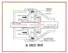
IN DIRECT DRIVE
- 03.PNG (58.78 KiB) Viewed 277 times
The overdrive gears are epicyclic and consist of a central sunwheel meshing with three planet gears, which, in turn, mesh with an internally toothed annulus.
All gears are in constant mesh. The planet carrier is splined to the input shaft and the annulus is integral with the output shaft.

- 05.PNG (18.06 KiB) Viewed 277 times
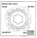
The extension of the gearbox main shaft forms the overdrive input shaft and power is transmitted by this to the inner member of the uni-directional clutch through a series of rollers which are driven up inclined faces and wedged between the inner member and annulus.
A coned clutch is mounted on the externally splined extension of the sunwheel and is loaded on to the annulus by a number of springs which have their reaction against the casing of the overdrive unit.
- 06.PNG (19.12 KiB) Viewed 277 times
The spring load is transmitted to the clutch member through a thrust ring and ball bearing. This arrangement causes the inner friction lining of the cone clutch to contact the cone of the annulus and rotate w ith it whilst the springs and thrust ring remain stationary.
Since the sunwheel is splined to the clutch member, the whole gear train is locked, permitting over-run and reverse torque to be transmitted. Due to the design of the sunwheel teeth, additional load is transmitted to the clutch member during over-run and reverse.
IN OVERDRIVE
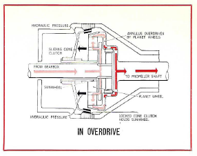
- 04.PNG (59.6 KiB) Viewed 277 times
On operation of the overdrive switch, the resulting build-up of hydraulic pressure causes the sliding cone clutch to move forward so that the outer friction lining is in contact with the brake ring. The sunwheel to which the clutch is attached is therefore held stationary.
The planet carrier rotates with the input shaft and the planet wheels are caused to rotate around the sunwheel and drive the annulus at a faster speed than the input shaft. The rollers of the uni - directional clutch are now driven down their inclined faces and are free to rotate.
THE HYDRAUliC SYSTEM
Hydraulic pressure is developed by a plunger type pump operated by a cam on the input shaft.
The pump draws oil from an air-cooled sump through a suction filter and delivers it via a non-return valve through a pressure filter to the operating pistons, solenoid valve and relief valve. Incorporated in the relief valve is a spring dashpot which ensures smooth overdrive engagement and disengagement under varying conditions. In direct drive a residual pressure of approximately 40 p.s.i. is maintained within the system and is controlled by a relief valve. When overdrive is engaged this is increased to a predetermined operating pressure.
Engaging Overdrive
When the solenoid is energised its valve opens and oil which is at residual pressure is directed to the bottom of the dash pot piston. This causes the dash pot piston to rise and compress the springs, causing a gradual increase in hydraulic pressure until the piston reaches its limit, by which time the relief valve spring has been compressed to its working length, thus giving full operating pressure. This pressure causes the operating piston to move forward overcoming the clutch return spring and engages the cone clutch with the brake ring.
Engaging Direct Drive
When the solenoid is de-energised, its valve is closed by a spring, cutting off the oil supply from the pump to the dashpot. Oil is now exhausted via the control orifice which allows the relief valve spring to relax to its direct drive condition. The dashpot springs continue to move the dashpot piston to its stop, allowing the system pressure to progressively drop which enables the clutch return springs to move the cone clutch gently into contact with the annulus.